+86 182 3185 8969
+86 182 3185 8969

Selecting epoxy coated wire mesh is not simply a matter of choosing a mesh number from a supplier’s catalog. For filter manufacturers, the wrong combination of mesh count, wire diameter and roll size can reduce liquid-flow or air-flow, make pleating unstable, increase material waste, damage filter media or cause coating failure during processing.
The correct specification must work as part of a complete filter structure. It needs to support the filter paper or synthetic media, maintain the required pleat shape, tolerate cutting and forming, and remain stable in the intended oil, air, humidity or outdoor environment.
This guide explains how to read an epoxy coated wire mesh specification, calculate approximate opening size, compare different wire diameters and determine a practical roll width and length for production. It also provides a purchasing checklist that filter manufacturers can use before requesting samples or placing a bulk order.
A complete specification normally includes more than the words “epoxy coated wire mesh.” At minimum, the purchase description should identify:
· Base mesh material
· Mesh count in both directions
· Bare or finished wire diameter
· Coating type and required performance
· Finished roll width
· Roll length or maximum roll outside diameter
· Core inner diameter
· Edge condition
· Color
· Required dimensional tolerances
· Packaging method
· Application and processing method
A typical description may look like this:
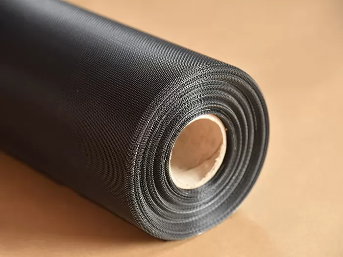
Q195 low carbon steel, oil-resistant epoxy coating, 18 × 14 mesh, 0.18 mm wire diameter, 1,000 mm roll width, 305 m roll length, black.
Each part affects how the mesh performs. Two products described only as “18 × 14 epoxy mesh” may be have differently if one uses a thinner wire, a heavier coating, a different substrate or a different heat-treatment condition.
The notation 18 × 14/0.18 mm generally indicates:
· 18 mesh in one direction
· 14 mesh in the perpendicular direction
· 0.18 mm nominal wire diameter
The first two numbers describe the number of openings or wires counted over one linear inch, depending on the supplier’s convention. Buyers should confirm the measurement method in the approved specification because terminology is not always used consistently across different markets.
When the two mesh counts are different, the mesh has rectangular openings rather than square openings. This is common in filter support mesh because the two directions can be designed to balance airflow, flexibility, strength and pleating behavior.
The orientation also matters. During production, the warp direction may be have differently from the weft direction. Therefore, a buyer should not only specify 18 × 14 mesh, but also confirm which direction runs along the roll length and which direction runs across the roll width.
This is especially important when the mesh is fed directly into a slitting or pleating line. Reversing the orientation can change feeding stability, bending behavior and pleat formation.
One of the most common purchasing mistakes is treating support mesh count as the filtration micron rating.
In many hydraulic, air, oil and fuel filter elements, the epoxy coated wire mesh is not the primary filtration medium. Its main function is to support filter paper, non-woven media or another fine filtration layer.
The filter media normally determines particle-retention performance, while the support mesh helps:
· Maintain pleat spacing
· Prevent media collapse
· Improve structural stability
· Protect the media during handling
· Create stable flow channels
· Resist pressure changes and vibration
A higher mesh count does not automatically produce a better filter. Increasing the mesh count usually reduces the pitch between wires. If the wire diameter remains unchanged, the clear opening and open area decrease.
This may provide more support points, but it can also:
· Increase airflow or liquid-flow resistance
· Increase material weight
· Make the mesh more difficult to pleat
· Reduce the effective filtration area
· Increase the possibility of media marking or deformation
The correct purchasing question is therefore not:
“What is the highest mesh count available?”
It should be:
“What mesh count gives the filter media sufficient support without unnecessarily restricting flow or complicating production?”
For a plain woven mesh, the theoretical pitch in one direction can be estimated as:
Pitch = 25.4 ÷ mesh count
The approximate clear opening before coating can then be estimated as:
Opening = pitch − wire diameter
For example, an 18 mesh direction with a 0.18 mm wire has:
· Pitch: 25.4 ÷ 18 = approximately 1.411 mm
· Approximate opening before coating: 1.411 − 0.18 = approximately 1.231 mm
For the 14 mesh direction:
· Pitch: 25.4 ÷ 14 = approximately 1.814 mm
· Approximate opening before coating: 1.814 − 0.18 = approximately 1.634 mm
The theoretical bare opening of an 18 × 14/0.18 mm mesh is therefore approximately:
1.231 × 1.634 mm
These calculations are useful for comparing specifications, but they are not a substitute for measuring the finished coated product.
The epoxy layer increases the finished wire diameter and slightly reduces the clear opening. Weaving tolerances, wire diameter tolerances, coating build and coating distribution also affect the final result.
Before approving a specification, ask the supplier whether the listed wire diameter refers to:
· The bare metal wire before coating
· The finished wire after coating
· An average measured value
· A nominal drawing value
This single detail can prevent major disagreements during incoming inspection.
The following calculations show approximate openings before coating. Actual finished openings should be confirmed using coated samples or an approved inspection report.
| Specification | Approximate Pitch | Approximate Bare Opening | General Selection Consideration |
| 18 × 14/0.18 mm | 1.411 × 1.814 mm | 1.231 × 1.634 mm | Balanced support and flexibility for many pleated filter structures |
| 18 × 16/0.25 mm | 1.411 × 1.588 mm | 1.161 × 1.338 mm | Stronger wire support with smaller openings |
| 12 × 10/0.25 mm | 2.117 × 2.540 mm | 1.867 × 2.290 mm | Larger openings combined with stronger individual wires |
| 22 × 10/0.16 mm | 1.155 × 2.540 mm | 0.995 × 2.380 mm | Directional support with significantly different opening dimensions |
This table demonstrates why mesh count and wire diameter must always be evaluated together.
An 18 mesh product woven with 0.16 mm wire does not provide the same opening, stiffness, weight or pleating behavior as an 18 mesh product woven with 0.25 mm wire.
Wire diameter affects much more than opening size. It influences stiffness, tensile behavior, weight, pleat formation, spring back and resistance to deformation.
Thinner Wire
A thinner wire generally provides:
· Higher open area when mesh count remains unchanged
· Lower material weight
· Greater flexibility
· Easier pleating around small radii
· Lower forming resistance
· More available filtration area within a fixed filter diameter
However, a wire that is too thin may not provide enough support for the media under pressure pulsation, handling or assembly loads. It may also deform more easily during slitting, unwinding or high-speed pleating.
Thicker Wire
A thicker wire generally provides:
· Greater structural rigidity
· Stronger resistance to crushing or distortion
· More stable support for heavy filter media
· Better resistance to handling damage
· Improved protection against mechanical impact
The trade-offs may include:
· Reduced clear opening
· Lower open area
· Higher roll weight
· Increased forming force
· Greater spring back
· More difficult pleating
· Larger minimum bending radius
The best wire diameter depends on both the filter design and the processing equipment.
A specification that performs well on a heavy-duty pleater may be too rigid for a high-speed line designed for softer mesh. Conversely, a highly flexible mesh may not provide the support required by a high-pressure hydraulic filter element.
A practical selection process should begin with the filter assembly rather than the mesh catalog.
1. Define the Function of the Mesh
Determine whether the mesh is used as:
· Inner support
· Outer support
· Filter media backing
· Pleat spacer
· Protective layer
· Structural screen
An outer protection layer may require greater resistance to impact and handling. A backing layer pleated together with filter paper may require greater flexibility and a smoother surface.
2. Identify the Filter Media
Record the filter media type, thickness, basis weight, stiffness and fragility.
Thin or delicate filter media may require closer and more uniform support points. Stiffer or multi-layer media may work with a more open supporting structure.
The mesh surface should not scratch, puncture or create unacceptable pressure marks on the media.
3. Confirm the Pleat Geometry
Provide the following information:
· Pleat height
· Pleat pitch
· Total number of pleats
· Filter element diameter
· Minimum bending radius
· Number of mesh and media layers
Tight pleats and small bending radii generally require a mesh that can fold without excessive spring back or coating cracks.
4. Check Flow Requirements
Do not evaluate airflow or liquid flow from mesh count alone.
Compare:
· Clear opening
· Estimated open area
· Number of support layers
· Filter media resistance
· Contact between the mesh and media
· Possible blockage caused by bonding or end caps
The support mesh should not become an unnecessary flow bottleneck. Its opening is usually much larger than the pores in the filter media, but an unsuitable specification can still reduce the effective flow area.
5. Review Mechanical Loads
Consider:
· Differential pressure
· Pressure pulsation
· Vibration
· Assembly compression
· Shock loads
· Handling during installation
· Cleaning or backwashing, when applicable
A hydraulic filter support layer may require more rigidity than a light-duty air filter backing.
6. Run a Production Trial
A drawing and theoretical calculation can narrow the available options, but a production trial is still important.
Test:
· Unwinding
· Slitting
· Feeding
· Pleating
· Cutting
· Edge sealing
· End-cap bonding
· Final assembly
Inspect both the wire mesh and the filter media after processing.
Mesh geometry cannot be separated from the base material because different metals have different density, stiffness, corrosion behavior and forming characteristics.
Q195 Low Carbon Steel
Epoxy coated low carbon steel mesh is commonly selected for hydraulic oil filters and other applications requiring reliable structural support.
It provides practical rigidity and good pleating compatibility when the wire drawing, annealing, weaving and coating processes are properly controlled.
Representative configurations include:
· 18 × 14/0.18 mm
· 18 × 14/0.16 mm
· 12 × 10/0.25 mm
· 22 × 10/0.16 mm
Low carbon steel mesh is generally considered when the main purchasing priorities are:
· Structural support
· Stable pleating
· Oil resistance
· Cost control
· High-volume filter production
The epoxy coating must remain continuous after slitting and folding because exposed low carbon steel may be vulnerable in corrosive environments.
5154A Aluminum Alloy
Epoxy coated aluminum alloy wire mesh is useful when lower weight, corrosion resistance and airflow are important.
It is often considered for:
· Industrial air filters
· Automotive air filters
· HVAC filter structures
· Lightweight filter elements
· Ventilation support screens
Representative configurations include 18 × 16 mesh with wire diameters such as:
· 0.23 mm
· 0.25 mm
· 0.28 mm
Aluminum alloy and low carbon steel do not behave identically during pleating. Even when their mesh count and wire diameter appear similar, they may have different stiffness, spring back, weight and forming characteristics.
A sample trial is therefore necessary when changing from steel mesh to aluminum mesh.
Stainless Steel
Epoxy coated stainless steel wire mesh may be considered for:
· Humid environments
· Chemical processing
· Marine conditions
· Outdoor installations
· Applications requiring greater substrate corrosion resistance
SS304 and SS316 are possible substrate options, but the additional material cost should be justified by the actual operating environment rather than selected automatically.
The buyer should also determine whether an epoxy coating is necessary over stainless steel. In some applications, the coating provides color, surface protection, processing benefits or compatibility with the filter structure. In others, uncoated stainless steel mesh may be sufficient.
The coating requirement should describe performance, not only color.
A black epoxy coated wire mesh from one supplier may not have the same chemical resistance, curing condition, flexibility or coating adhesion as a visually similar product from another supplier.
Oil-Resistant Epoxy Coating
For hydraulic and oil filtration applications, the buyer should specify:
· Hydraulic oil type
· Oil brand or reference fluid
· Operating temperature
· Maximum temperature
· Exposure duration
· Pressure conditions
· Acceptance criteria after immersion
A general statement such as “oil resistant” may be insufficient because hydraulic oils, additives, temperatures and service conditions vary.
The agreed inspection criteria may include:
· No blistering
· No visible peeling
· No softening
· No discoloration beyond the agreed limit
· No exposed substrate
· No unacceptable reduction in adhesion
Weather-Resistant Coating
For window screens or exposed industrial equipment, the buyer may need to evaluate:
· Humidity resistance
· Salt-spray resistance
· Ultraviolet exposure
· Temperature cycling
· Surface color stability
· Corrosion around cut edges
The test method should match the final environment. A short laboratory salt-spray test may be useful for comparison, but it should not be treated as a direct prediction of service life in every climate.
Coating adhesion is especially important for filter manufacturers because the mesh may pass through:
· Slitting knives
· Guide rollers
· Tension rollers
· Pleating tools
· Cutting equipment
· Pressing equipment
· Heat-curing processes
A coating that looks acceptable on a flat roll may crack, peel or expose the substrate after repeated bending.
Relevant quality checks may include:
· Surface appearance inspection
· Coating thickness measurement
· Pencil hardness testing
· Impact resistance testing
· Scratch resistance testing
· Bend or mandrel testing
· Repeated-flexing or anti-fatigue testing
· Oil immersion testing
· Salt-spray testing for outdoor applications
The buyer and supplier should agree on the test method, acceptance criteria and sample location before mass production.
Roll width affects material utilization, line speed, slitting cost and production waste.
The most economical width is not always the widest available width. The best width usually matches the filter media, pleating machine and slitting plan with the least edge waste.
Use the following process:
1. Determine the required finished strip width.
2. Add the necessary trimming allowance.
3. Check the maximum usable width of the pleater and slitter.
4. Decide whether one master roll will be slit into multiple strips.
5. Calculate edge waste for each proposed master width.
6. Confirm the permitted width tolerance.
7. Define the required edge condition.
8. Verify the warp and weft orientation.
For example, suppose a production line requires three finished strips of 310 mm.
If each strip requires approximately 5 mm of total trimming allowance, the purchasing department should calculate the master roll width around the actual slitting plan rather than ordering a generic 1,000 mm roll.
A poorly planned width may create:
· Excessive edge waste
· An unusable narrow leftover strip
· Additional slitting operations
· More roll changes
· Higher conversion cost
· Feeding instability
Available epoxy coated wire mesh widths commonly range from narrow slit rolls to master rolls up to approximately 1,500 mm, depending on the material and specification.
However, a very wide, fine or soft mesh can be more difficult to keep flat and stable. Maximum width should therefore be confirmed for the exact mesh count, wire diameter, base material and coating system.
Roll length is not only a shipping detail. It affects production efficiency, roll weight, handling and compatibility with the unwinding equipment.
Longer rolls can reduce:
· Roll changes
· Line stoppages
· Material joints
· Setup time
· Packaging per square meter
However, they also increase:
· Roll weight
· Outside diameter
· Lifting requirements
· Unwinder load
· The risk of winding deformation
Before selecting roll length, confirm:
· Maximum roll weight accepted by the line
· Maximum roll outside diameter
· Core inner diameter
· Core material
· Core wall strength
· Required winding tension
· Maximum number of joints
· Whether splice locations must be marked
· Packaging orientation
· Pallet or crate limitations
For high-volume filter production, fewer roll changes can improve efficiency. However, an excessively heavy roll may create feeding problems or require lifting equipment that is not available at the plant.
Roll length tolerance should also be stated. If purchasing is based on square meters, define how length, width and invoiced quantity will be measured.
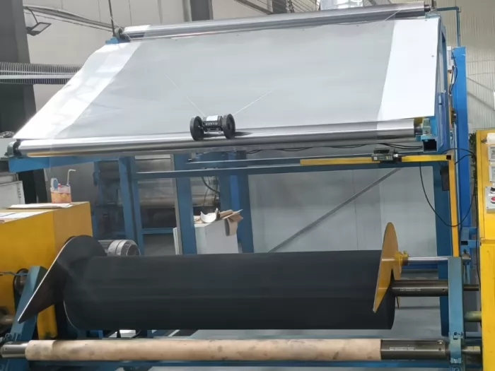
The paper or plastic core must match the expanding shaft or unwinding system used on the production line.
The buyer should provide:
· Required core inner diameter
· Maximum core outer diameter
· Core length
· Core material
· Maximum roll weight
· Required winding direction
Poor winding can cause:
· Telescoping
· Edge damage
· Uneven tension
· Mesh deformation
· Feeding problems
· Coating abrasion between layers
A roll that meets the required mesh count and width may still be unsuitable if the winding is too loose, too tight or uneven.
Edge Condition and Slitting Quality
The roll edge directly affects feeding stability, filter media protection and operator safety.
Poor slitting can leave:
· Projecting wires
· Loose coating
· Uneven width
· Curled edges
· Sharp wire ends
· Local mesh deformation
Specify whether the order requires:
· Slit edges
· Natural woven edges
· Selvaged edges
· Rough edges
· Trimmed edges with a defined projection limit
For mesh pleated together with filter media, stable edges are especially important because projecting wires can tear filter paper or interfere with machine guides.
Inspect the first and last section of each roll as well as material from the middle. Edge quality and winding tension can vary along the roll.
A controlled approval process reduces the risk of receiving dimensionally correct mesh that does not run well on the production line.
Step 1: Submit Application Data
Provide:
· Filter type
· Filter media
· Working fluid
· Operating temperature
· Pressure conditions
· Pleater type
· Pleating speed
· Required roll size
Step 2: Compare Candidate Specifications
Evaluate at least two practical combinations when developing a new filter.
One option may favor:
· Flexibility
· Open area
· Low weight
Another may favor:
· Rigidity
· Impact resistance
· Stronger media support
Step 3: Approve a Physical Sample
Do not approve the product only from a specification table.
Measure:
· Mesh count
· Wire diameter
· Finished coated diameter
· Opening size
· Roll width
· Surface appearance
· Coating condition
Step 4: Conduct a Production-Line Trial
Run the sample through normal slitting and pleating conditions.
Avoid using unusually slow trial speeds that could hide feeding, tension or coating problems.
Step 5: Inspect the Finished Filter Element
Check:
· Pleat uniformity
· Filter media damage
· Coating cracks
· Exposed metal
· Springback
· End bonding
· Final dimensions
· Flow performance
Step 6: Create an Approved Reference Standard
Retain:
· A signed sample
· Technical drawing
· Inspection report
· Agreed tolerance table
· Packaging example
The approved standard should state permitted tolerances rather than only nominal values.
When receiving epoxy coated wire mesh, inspect the following items.
| Inspection Item | What to Confirm |
| Base material | Correct substrate grade and traceable batch |
| Mesh count | Correct count in both directions |
| Mesh direction | Warp and weft orientation matches the order |
| Wire diameter | Measurement basis is clear: bare or coated |
| Opening size | Within the agreed tolerance |
| Roll width | Consistent across the roll |
| Roll length | Meets the purchase tolerance |
| Surface condition | No major pinholes, bare areas, lumps or contamination |
| Coating adhesion | No unacceptable peeling after the agreed test |
| Flexibility | No cracking during specified bending or pleating |
| Edge quality | No dangerous or media-damaging wire projections |
| Flatness | No severe waves, folds or local deformation |
| Core and winding | Correct core ID and stable winding |
| Packaging | Protected from moisture, impact and crushing |
Sampling frequency should reflect order size and process risk.
For a new specification or new supplier, a more intensive incoming inspection is advisable before the material is released to full production.
Ordering by Mesh Count Alone
“18 mesh” does not define:
· The second mesh direction
· Wire diameter
· Base material
· Coating system
· Roll format
· Mesh orientation
Confusing Support Mesh with Filter Micron Rating
The filter media normally determines filtration efficiency. The epoxy coated mesh primarily supports and protects that media.
Ignoring Coating Build
The coated wire is thicker than the bare wire. This reduces the finished opening and can change flexibility and pleating behavior.
Choosing the Widest Roll Without a Slitting Plan
This can increase edge waste, roll weight and handling difficulty rather than reducing cost.
Approving a Flat Sample Without Pleating It
Many coating and forming problems appear only after cutting, bending and repeated pleating.
Failing to Define the Core and Outside Diameter
A roll may meet width and length requirements but still be incompatible with the buyer’s unwinding equipment.
Ignoring Mesh Direction
Rectangular mesh may behave differently when rotated by 90 degrees. The roll direction must be included in the approved specification.
Comparing Price per Roll Only
Buyers should compare:
· Usable square meters
· Edge waste
· Number of splices
· Roll consistency
· Rejection rate
· Production speed
· Finished filter quality
A cheaper roll can create a higher total conversion cost.
To receive a technically useful quotation, provide:
· Application: hydraulic filter, air filter, oil filter, fuel filter or other use
· Base material preference
· Mesh count in both directions
· Wire diameter
· Whether the diameter is bare or coated
· Required coating performance
· Coating color
· Finished width and tolerance
· Roll length or maximum roll weight
· Core inner diameter
· Edge requirement
· Warp and weft orientation
· Annual or monthly quantity
· Required tests
· Compliance documents
· Sample size
· Current drawing or specification
· Description of any existing production problem
When the exact specification is unknown, send the filter drawing, media information and processing requirements.
A technically capable supplier can then recommend candidate specifications for testing rather than guessing from a mesh number alone.
Is a Higher Mesh Count Always Better?
No. A higher mesh count provides more wires and smaller openings, but it may reduce open area and increase forming resistance.
The best mesh count balances:
· Media support
· Flow
· Mechanical strength
· Pleating performance
What Is the Difference Between 18 × 14 Mesh and 18 Mesh?
An 18 × 14 specification has different counts in the two directions and therefore produces rectangular openings.
“18 mesh” alone is incomplete unless the product is confirmed as 18 × 18 square mesh.
Should Wire Diameter Be Measured Before or After Epoxy Coating?
Both measurements can be useful, but the purchase specification must clearly state which value controls acceptance.
The bare diameter affects the woven structure, while the finished diameter affects the coated opening and overall thickness.
How Do I Choose Between Q195 Steel and 5154A Aluminum Mesh?
Choose according to:
· Required rigidity
· Product weight
· Corrosion resistance
· Filter type
· Pleating behavior
· Operating environment
Low carbon steel is often selected for stronger hydraulic filter support, while aluminum alloy is frequently considered for lightweight air filtration structures.
Can Roll Width and Length Be Customized?
Yes, but feasible dimensions depend on:
· Mesh count
· Wire diameter
· Base material
· Coating process
· Winding stability
· Production equipment limits
Confirm the exact specification rather than assuming every mesh structure can be supplied at the same maximum width or length.
Why Does the Finished Opening Differ from the Calculated Opening?
The theoretical formula normally uses nominal mesh count and bare wire diameter.
The finished opening may be smaller because of:
· Epoxy coating thickness
· Weaving tolerance
· Wire diameter tolerance
· Coating accumulation at wire intersections
· Measurement method
Should I Request a Sample Before Placing a Bulk Order?
Yes. A sample allows the buyer to verify dimensions, coating condition, flexibility, slitting behavior and pleating performance before committing to a large-volume order.
The most reliable epoxy coated wire mesh specification is the one that performs consistently in the buyer’s actual filter design and production process.
Mesh count establishes the support pattern. Wire diameter controls the balance between rigidity and open area. Roll width and length determine whether the material can be converted efficiently.
Begin with:
· Filter media
· Pleat geometry
· Operating environment
· Flow requirements
· Mechanical loads
· Equipment limitations
Then calculate the approximate opening, compare candidate mesh structures, inspect a finished coated sample and conduct a normal-speed production trial.
This approach is more dependable than selecting epoxy coated wire mesh by mesh count or price alone.
For custom epoxy coated wire mesh rolls, Jiushen supports specification development based on filter application, mesh structure, wire diameter, coating performance, roll width, roll length and processing requirements. Send your current specification, technical drawing, sample or production parameters to receive a targeted recommendation and quotation for trial or bulk supply. Contact us right now!
Copyright © Hebei Jiushen Wire Weaving Co., Ltd. All Rights Reserved. |
Sitemap
| Technical Support: